@skezo , looks like I will be machining the first couple sets on my cnc mill. I’m not geared for production runs of machined parts, I’m an idea prototyper and product developer…so mostly one-of machined parts.
This first production run of the z-axis stabilizer mod will be priced at $65.00USD to get the ball rolling. I’ll machine 5 sets this time. This initial price will include stainless-steel fasteners, lockwashers and shims. This first production-run price will change if there is a second batch produced at a machine-shop.
This morning I met with 2 machine-shops with the mods I use on my Cetus printer and asked for a ball-park cost. Their verbal cost(not guaranteed) estimate is roughly $80.00 each when producing quantities of 25 sets per batch. This ball-park cost is only for the machining and does not include any post-processing such as a nice-looking surface finish.
If any other Cetus owners are interested please let me know soon, as the price will likely be much higher if batch quantities produced at a machine-shop are less than 25 sets per batch.
@skezo , let me know if you want to order a set and we can set-up payment via private message.
@skezo, There is a way to reduce the cost for folks wanting to have a local machine-shop in their area produce the parts for the z-axis stabilizer mod I’ve designed.
The idea I have in mind will substantially reduce the setup charge ($45 - $65USD) that all machine-shops build into the overall cost.
This idea would involve a little work from folks to get the aluminum bars to the point where the machine-shop would simply perform the machining operations without much setup, effectively reducing that huge setup charge.
I’m thinking of creating a thin sheet-metal template etched and cut with a laser. The drilling locations would have a tiny laser-cut hole where folks could simply center-punch the location, near the hole would be laser-etched dimensions and specific instructions.
The template would be cut to the size the aluminum bar needs to be with any angles included, near the angle would be laser-etched instructions. To reduce the material costs(shops usually profit by providing the materials), folks could take the templates to a local metal supplier to have the aluminum-bar lengths precision-cut.
The other cost effectively reduced is shipping from my shop.
@incrediblej1 , sorry for the late response. I’ve been battling with a sophisticated attack on my business server. An incredulous story for sure… the attack completely crippled my online business activities, long story short… we caught the hacker…a tenant in the apartment building…my neighbor!
Yes, this project is re-activated now that I have regained control of my business services.
It is my understanding the structural backbone of the MK3 has not changed from the MK1/MK2.
Are you interested in purchasing the sheet-metal template or the finished ready to bolt-on stabilizer mod?
@dar303 , Thanks for the interest! I’ve experienced a few setbacks getting mod kits ready for sale. Looks like there will be a few kits ready by Jan 30th. I’ll contact you when I have a kit ready for you.
I increased the first batch quantity twice last week and again yesterday. The quantity was based on those that strongly confirmed they would like a kit.
@skezo I got the feeling you had lost interest because I did not receive a reply from you. I currently have 4 extra kits available in this first batch. If you let me know before they are gone I will put your name on one.
@incrediblej1 are you still interested in committing to a mod-kit?
This first batch will be ready within the next week.
Thank-you for the confirmation @skezo , you are definitely in on the first batch!
Also thank-you for your patience, it’s been painfully slow to get this mod-kit ready for folks. I had hoped to have a machine-shop make the stabilizer parts because I suffer severe pain from a car accident and don’t have many good hours in a day to machine the parts myself. If demand becomes unmanageable I will have to contract a machine-shop to make the parts and the cost will likely double.
Hi @incrediblej1 , I’m trying to keep the cost as low as possible. A typical machine shop is over $100. I’m almost done machining 18 sets and thinking the price will be around the $65 mark. If folks would like to use their own fasteners, lockwashers, brass-shims and tnuts, the price would be lower by $8-10. The expansion board is easily re-located on the stabilizer mod or the z-axis extrusion.
I’ll design a printable mount to relocate the expansion board, I’m thinking of many different solutions. I see the relocation of the expansion board as a minor inconvenience compared to the performance upgrade of the z-axis stabilizer mod.
Brent I just wanted to say thanks for the heater block bolts tip. My bolts were not loose but also not very rigid and I could see some artifacts.
Worrying about overtightening and stripping the heater block threads, I bent up a 1mm stainless steel wire hanger. It loops around the top notch of the cold end while the other wire end secures to the extruder printed drive gear assembly which is now printed in ABS. I repaired my original MK2 extruder.
Another simple mod is moving the extruder printed belt attachment part to the top side of the belt. I mirrored the Cetus STL file and printed it in ABS. You need to reverse the polarity of one stepper phase to make the software happy. The motivation was that I built a heated ultrabase glass bed and found the original Cetus PLA part got very soft when using ABS bed printing temperatures which for my setup is 115 to 150C. I believe all the Cetus printed motion parts need to be printed out of polycarbonate, PEI or machined out of metal if printing on a heated build surface.
@peter101 , tks for the comments and the tip about the belt attachment, I believe that attachment should be a thin stainless-steel part…your solution works for sure tho!
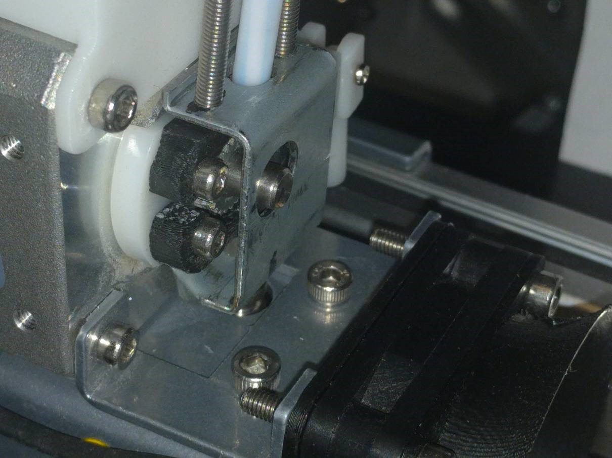
Even though you have comfortably tightened the heater block bolts the problem still exists. The bolts inside those stainless steel tubes are too small for the forces being applied and the threads will easily strip and become damaged. I installed a larger bolt size, but even a larger bolt size only gets you part-way to a rigid filament extrusion system. If you browse earlier posts in this thread you will find a picture of my modified extrusion delivery system. I added an aluminum post that anchors the nozzle…this aluminum post solves soooo many problems and allows the extrusion-motor to do its job precisely. If the nozzle is rigid then retraction works properly…precisely… and exactly when retraction is needed.
If the nozzle-height is rigid throughout the entire print process you will no longer experience a nozzle collision with previously printed areas/layers of the part being printed. Although, if the z-axis is not rigid then the nozzle-height will fluctuate throughout the print job, I guarantee you would be surprised at how much!
A rigid nozzle-height solves many other issues, too numerous to list here at this time. I’ve been struggling with some pain flare-ups which keep me from being in my shop and getting those stabilizer-mods finished for the folks patiently waiting.
I should have you over to my shop Peter, you could see the mods and the quality of prints they allow!
A meeting of minds. The print improvement is amazing. With my first rev I could see some nozzle motion so I ditched the quick and dirty wire and bent up a proper steel bracket yesterday. Then I lied to the printer slicer software choosing a 0.2mm nozzle while a 0.4mm was actually installed. This cheat allows selection of a 0.05mm layer height with a 0.5mm paving width, my typical paving width. In the past the result was bad and I can see why Tiertime choose to limit the minimum layer height, however, I am shocked how good the surface is now! Just for a start the purge line converges to a constant width and gone are any width oscillations which I previously thought were software purge line “features”. Funny how one’s mind can rationalize chaos. But in truth all printer improvement is just peeling an onion and exposing yet another limitation, which ultimately is the slicing software. This mod was a lot of layers - Thanks again.
I post printable designs on thingiverse as peter120.
@peter101 , excellent mod you have there. I was going to machine a part to do what you have done, but then decided to design the nozzle-post mod as the beginnings of a quick-change nozzle idea I have in mind. So each filament color/type would have a nozzle assigned and is easily swapped out in 20-30 seconds.
You’ll be amazed when you see the speeds I’m printing at without loss-of-quality. Once the nozzle is locked-down, the z-axis stabilized and the y-axis mods installed it completely changes the Cetus printer’s capabilities…accuracy with speed!
Where your bracket meets the top of the nozzle, did you fill the space so pushing and pulling are stabilized?
Machining was my first thought and it is interesting that you ask about a spacer, that was plan B and was not implemented.
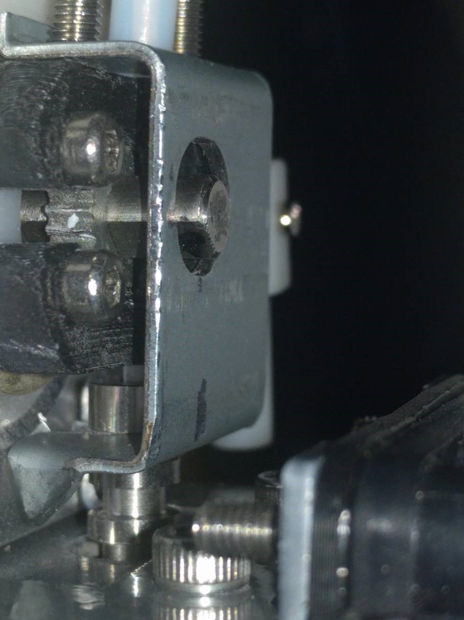
With the filament extrusion temp set very low to 50C (that is not extruding) the mark 2 extruder has a nozzle down deflection of 0.021mm and up deflection of 0.004mm. This measurement was made using the maximum force that this feed mechanism can generate. The screws in my pic were adjusted to pull up the nozzle up 0.2mm which pre loads the nozzle support bracket and the horizontal heater bolts. Using a proper extrusion temp the nozzle deflection will be much less. As is the cold deflection is fine for printing 0.050mm layers.
I designed a very nice quick release filament spool holder for flexible filaments but it required Z hop to print. Long story but I have a duet2 WIFI to control the Cetus when needed. A bonus is the IKO rails actually have a longer travel length of about 193mm which is handy if I ever need a slightly larger build volume. You might want to consider duet for controlling a second extruder and some additional fans. I have thought about a second extruder for supports but the onion thoughts kick in and any improvement ideas that I have get put on a shelf.
I am more into accuracy rather than speed because I am creating functional parts and it typically takes longer to design things than it takes to print them.
BTW the mk3 metal nozzle heater can not reach ABS+ raft temperatures using the stock power brick.
I’m using Simplify3D to micro-manage the print jobs which allows for some amazing fine-tuning and advanced print control. I haven’t upgraded any components on my rig as I wanted to make sure the mods I designed would allow folks to bolt-on the mods and be done…increasing the accuracy and allowing for speedier prints. I have an Azteeg board and a BondTech extruder system I’ll install sometime soon. I’ll off-load the filament extruder from the y-axis with a floating Bowden setup.
All of my printing is functional prototypes, so accuracy has always been my goal…a side effect is the ability to print at speeds of 120+mm/sec for proof-of-concept or larger models with larger features not requiring much directional changes.
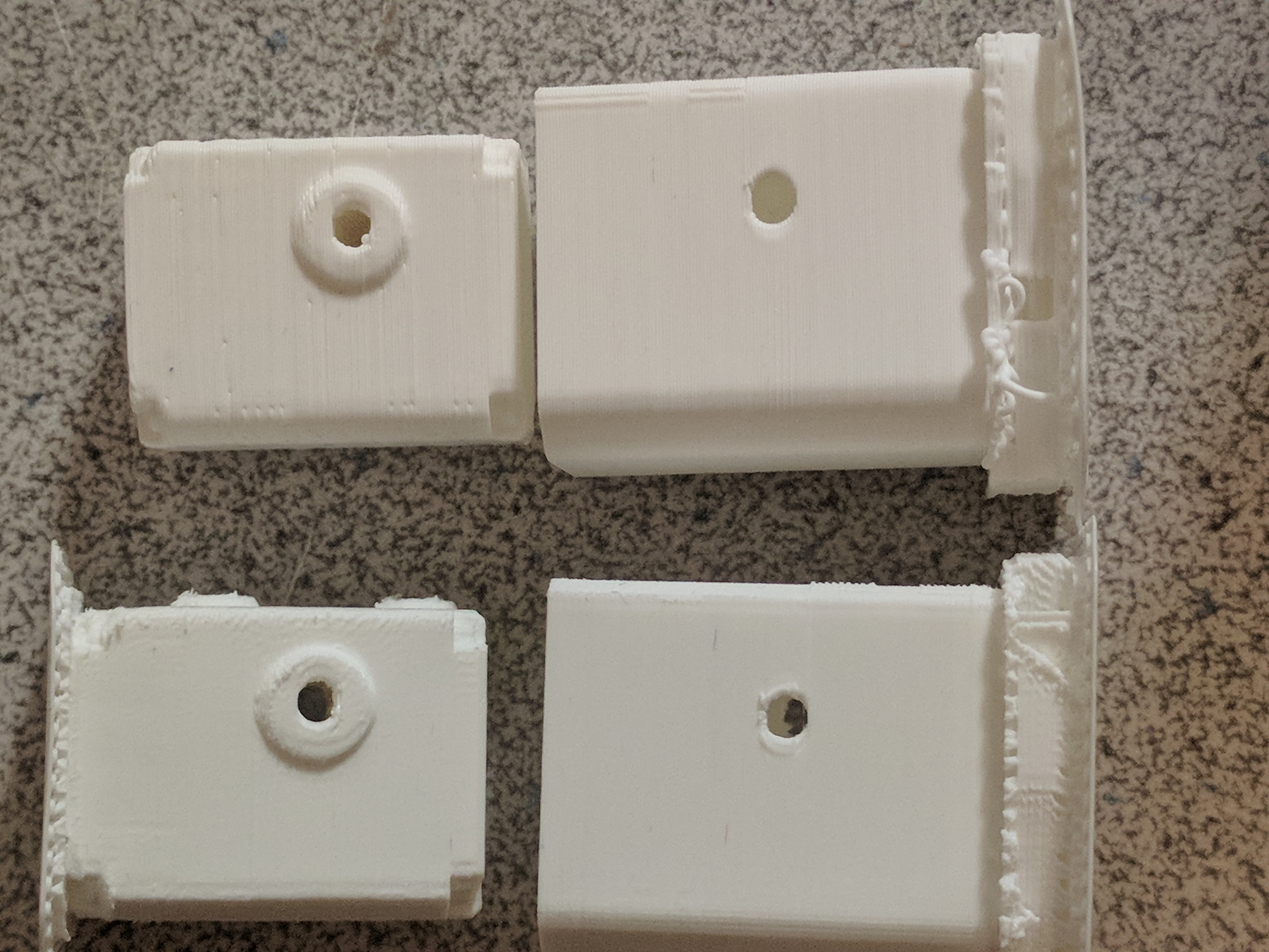
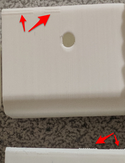
The reason I mentioned the spacer is I noticed in your last photo, the white printed model on the bottom right has some layer lines not aligned with the rest of the model above the hole at the edge. There are a few reasons for those artifacts, but usually it’s the nozzle tip being deflected around a small blob where the layer starts/ends.Usually fine-tuning nozzle retraction will keep those layer lines where they should be and result in a nice crisp edge to the model. So, if the nozzle is allowed to be pulled upwards during a retraction command, retraction will not execute properly and produce those layer-lines kicked outwards from where they should be. It’s for that reason among others I decided to go with the nozzle-post. The nozzle-post also lowers the heat-zone closer to the heater-block, we all know what happens when there’s too much heat migrating up the stainless-steel upper nozzle throat.
Brent I like the way you think and I like your mods. I guess it is to be expected that a few users will care more about a product that the manufacturer.
I am reasonably certain the hole artifacts you see are because I told the slicer that I had a 0.2mm nozzle to get the 0.05mm layer printing option available (I was if fact printing with a 0.4mm nozzle). Looking at the slicer tool path generated for a 0.2mm nozzle printing a 0.45mm path or paving width, it takes a wiggle at edges.
Previously I got all my filaments from the Hobby King warehouse in Oregon. Makers Muse suggested that they had good filaments and Angus was correct, until they changed manufacturers. Fast forward I have several spools of truly mediocre filament that I want to use up and if I wasn’t so stubborn I would just toss them out. Some brain dead manufacturer in the EU shrink wrapped the filament with a descant and then perforated the shrink wrap with ventilation holes! The filament has more problems than water but I currently get a better surface finish with a 0.05mm layer and the wiggle artifacts I can live with.
I just kludged up a polycarbonate filament drying system using a pressure cooker connected to a vacuum pump. I expect to print with PC this weekend, wish me luck.
FWIW: To get an idea of the extruder heater headroom measure the RMS voltage across the heater. The maximum voltage across my Cetus heater is 18.4V, and with max voltage or no temperature regulation it gets to 275C using the older nosier 10CFM fan while not actually extruding any filament. I designed a laminar fan input duct which eliminates a big bunch of the annoying noise and I like the better print cooling. You could look at this intrinsic maximum temperature as a safety feature, I don’t but you could.
Peter, I should have clipped a screenshot instead of using text to pinpoint the area I was referring to, guess I sometimes like the challenge of using less than a thousand words to get there, sorry I wasted valuable time for both of us!
The slicer tool path creating a wiggle, interesting…is that slicer event happening for all 90deg and tighter corners or for all corners? You’ve successfully peaked my curiosity!
Yeah, have to wonder how the heck someone decided to include ventilation holes in that shrink wrapped filament… maybe they were having a pasta-brainfart from the night before when preparing the left-overs for the refrigerator.