"Speed for the Need" - a mod-package increasing print-accuracy on the Cetus

I decided to visit a local machine shop to get advice on the most economical method to connect several mod-parts. Even though I have a precision cnc mill and lathe, a second opinion is always a good idea. I’m making a small change to lower the cost of machining the z-axis stiffener, so a few more days will pass before the reveal.

A few months ago I contacted a 3D filament distributor about extrusion tolerances and mentioned I was tentatively planning an “Internet Contest” around the first-look video for the z-axis stiffener, they expressed interest and offered prizes of 10 spools of filament and 3 filament-spool “smart” containers that dehumidify as needed. I’d love to follow through with the contest, would be a ton of fun for participants.

cheers!

Ah, I imagined that the mods are all 3D printed, but of course very precision and stiffness is key, plastic doesn’t cut it always I suppose :slight_smile:

Cool thing with the contest! Will have to think up a nice little demo project, sound like fun!

Thanks for the update and sorry for the slow answer rate here…

@superhans , there’s just no-way to properly stiffen the backbone without at least aluminum. Even the stainless-steel base everything attaches to is quite flexible, not so noticeable without appropriate measuring devices.

I have several mods that stiffen the extruder axis, but they are not the ultimate solution. The problem is the aluminum extrusion, while it does provide a convenient and inexpensive structure to attach things to, it’s not designed to provide a backbone for linear motion. It’s use keeps these printers affordable and within the reach of school budgets and those without deep-pockets…kudos to Tiertime!

The z-axis 3D printed belt-connector finally gave-up on my printer. Was thinking of using aluminum and mill a new belt-connector but decided to use Delrin and fatten the connector to mate with the side of the linear-guide, thereby decreasing the stress on the connector. Feels like machining butter.

I kinda fell into another rabbit-hole, have a tougher extruder axis in-mind and will allow for a print-bed of around 220-230mm’s…tis tempting, …but…must…resist!

cheers!

Yeah, I guess those aluminum extrusion are merely the cheapest and lightest way to get something that is fairly stiff via their profile, but probably not the ultimate solution. You gotta post a photo of your new connector replacement. I googled Delrin (never heard of it before), but can’t yet imagine how you make use of it.

And yes please resist the next rabbit-hole at least for a bit :slight_smile: Thoroughly enjoying your posts though, always packed with things I have not much experience with yet.

Cheers!

1 Like

Delrin features…

  • Excellent dimensional stability -outstanding abrasion resistance among thermoplastics and metals, so when mated with the linear-guide, the mating surface dimensions will remain stable for longer periods. Very low moisture absorption -consistent properties means less fastener creep. Moisture, lubricants and solvents including gasoline and gasohol have little effect, which is important in parts incorporating self-threading screws or interference fits.

  • Continuous use temperature of 180°F -retains much of their toughness through a broad temperature range… so very little fastener creep allowing the screw to remain locked at the desired torque for longer periods.

  • Easy to machine to close tolerances, I strive for less than .0005" tolerance over 5 inches.

***high tensile strength, stiffness, resilience, fatigue endurance and a low coefficient of friction against metals

The next version I’ll wrap it around the corner of the z-axis in the photo. This will help reduce the vertical yaw movement of the linear-guide on the rail. You might be surprised how much the yaw movement has on the line-width tolerance.

The yaw tolerance of the linear-guide block is a huge variable when leveling the y-axis to the print bed. The question then becomes, when leveling… perform this procedure when the y-axis motor is energized(powered) or not-energized? The most accurate method is when the motor IS energized!

cheers!

I’m posting this pic hoping it will help others with their ongoing mysterious printing issues, specifically the problems @rogermc has been experiencing here

I was planning on providing sufficient documentation along with any reveal-pictures of my MKII printer setup, but time is passing too quickly these days and I’m experiencing very tough days with severe pain from a car-accident many moons ago…so this picture is posted without supporting documentation. Heck, I was even planning an Internet Contest with many cool prizes along with the introduction of my collection of mods for this printer.

Interestingly, in the last post above, the photo of the Delrin belt-connector also shows another simple mod that increases print-accuracy when combined with other mods I’ve designed for the extruder assembly. I purposely set the camera-focus on that part instead of the Delrin connector :wink: , you know…for the fun of it … and maybe even some aha moments for folks.

Improving/designing industrial and general consumer products has been an enjoyable focus for many decades, I’m not going to waste any of my time or yours discussing where I’ve been professionally to support my works. I’ll just say “I’ve kinda got-a-knack for a bunch-of-differing-stuff” :sunglasses:

Ok, enough rambling…

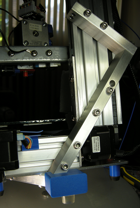
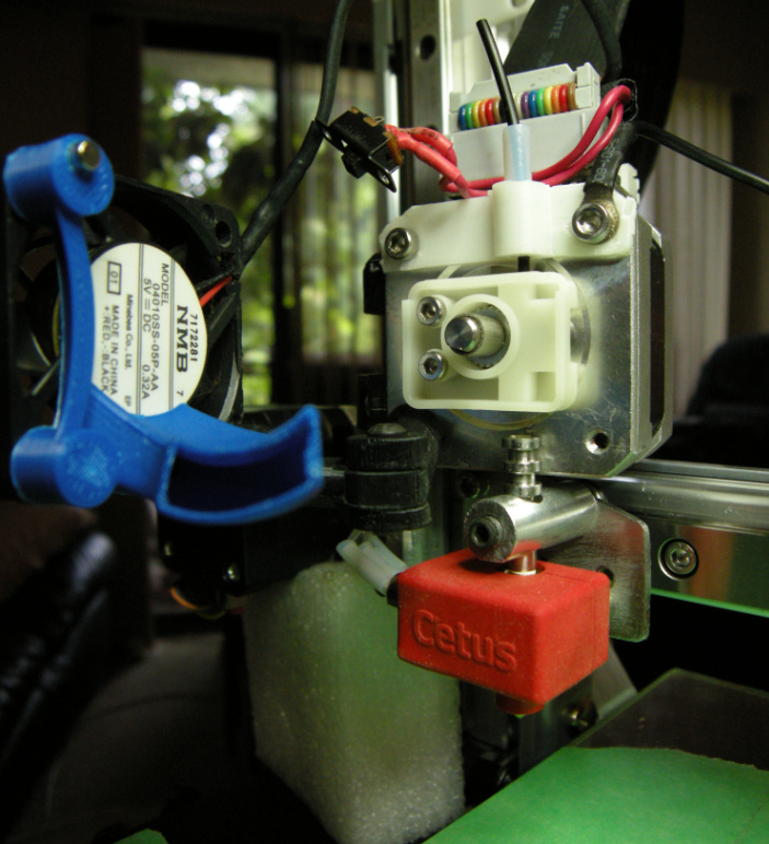
above: extruder motor adjustable in the vertical and horizontal, nozzle and heater-block adjustable in the vertical and horizontal, fan/duct assembly swings in all-directions. Rock-solid nozzle-mount provides for extremely accurate retractions, layer-height, layer-width and vertical alignment. The vertical position of the nozzle is one of the most important preventative maintenance tasks on-the-list of things-to-do for error-free and accurate printing. The round aluminum holding the nozzle also lowers the top-of-the-heat-zone in the nozzle. Securing, aligning and cleaning the nozzle is by-far the best things you can do to your printer in your quest for reliable/accurate prints from your Cetus. The filament you see loaded is Ninjatek Armadillow.

image

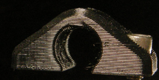
I just printed my first model with the Armadillow filament, the only problem I have is I’m experiencing too much temperature-swing …this filament has a very-tight temperature tolerance and is the reason why the photo above has surface artifacts and the bridging somewhat failed(among many other reasons)…while printing I had to turn the fan on-and-off repeatedly to keep the temp within the 4 degrees celsius tolerance needed for the quality I’m looking for.

The above photo is printed using 3 layer-heights, .30mm, .20mm and .10mm , 3 different layer-widths, .40mm, .50mm and .60mm respectively. There are also 2 different infill line-widths along with 2 different infill patterns. Using these settings has allowed for rigidity where needed, and extra vibration/frequency -dampening where needed on these extruder motor-mounts.

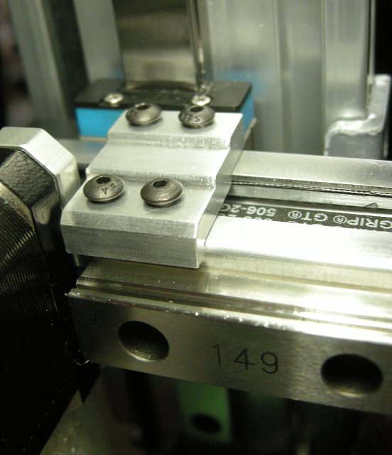
July5 add : Oh…the chamfer you see in the photo above only exists on this side, the other side is a 90degree edge… the chamfer works with some of the interior structures.

July6 add: you may notice the head of the socket-head screw, just to the right, in the rail, is closer to the surface of the rail compared to other rail fastener heads. This screw is 6/32" x 20mm long, the screws main function is to lessen the horizontal axial-torque in the extrusion. When you provide ultimate-strength stabilization to the nozzle assembly, z-axis tower and x-axis, you are now left with the lesser noticeable structural forces/variables governing print-quality…axial-torque and linear guide-block tolerances. The 6/32" x 20mm fastens the guide-rail to the other side of the y-axis extrusion arm…there are 3 locations I’ve employed y-axis axial-torque limiters.

These lesser forces are difficult to measure, they happen quickly and are not noticeable when they happen unless you use lasers to measure the movements. I have also found the effects of these forces on print-quality are less noticeable on thicker layer-heights of .30mm and above. I’ll try and prepare some visuals.

update: heating issue, solved …it’s been awhile since checking the heat-block thermal paste, re-applied a nice blob in each hole and re-inserted the heating components…back in business!

cheers and good journeys folks!

Ha, I suspected you angled the stepper and mounted it on top of the y-axis! No force twisting that axis anymore :wink: 
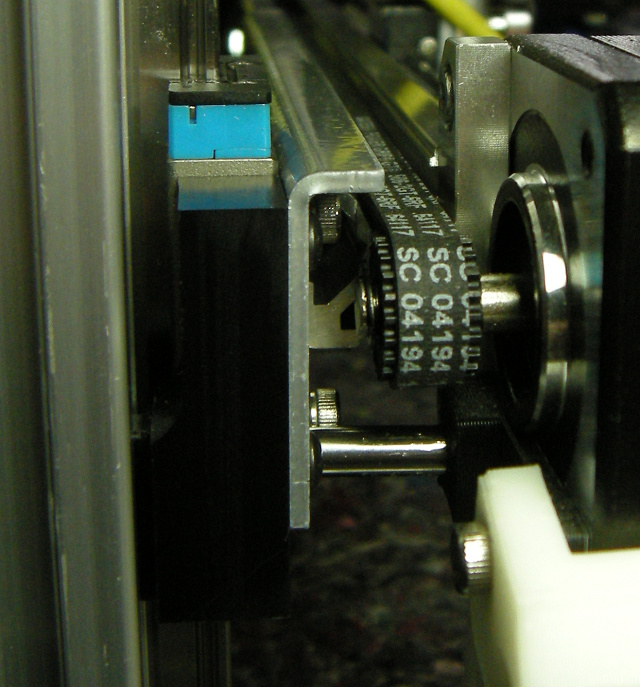
The extruder and fan setup is unexpected! Very cool, especially how much visibility you gain to observe the print run. Nice! Still many things to discover, how you mounted the motor for example and how many parts it requires, separate mounting brackets for the motor and extruder plus the holder rod.

Regarding the 6/32" x 20mm screws, did you drill extra holes in the extrusion profile? I mean that is the easy part, good thing there are spare holes in the guide rail :slight_smile:

Looks very promising, thanks for the updates!

PS: And Delrin has a really strong feature set! Good to know!

A quick pic from another post I made recently…

Yes I drilled holes through the extrusion and tapped threads into the extrusion nut used by the y-axis steel bracket.

This method dampens the axial torque a fair amount, but is not the ultimate solution. The ultimate solution would be to get rid of the extrusion and use an aluminum profile with much higher strength in all planes where unwanted torque exists. Once I have the z-axis mod published I will be prototyping a design I have in-mind for a y-axis better suited for cantilever style printers and solves the extruder-weight and inertia problem that twists the currently-used extrusion material/profile … possibly allowing for a larger print-bed.

Last week I designed a mod that further stiffens and limits the twist effect this type of aluminum extrusion and y-axis design allows …

This one is not a simple bolt-on mod! Requires the faces of the extrusion to be milled absolutely flat and square along with the steel bracket. Because the top bend of the steel bracket is not at 90degrees to the z-axis like the bottom bend, I had to remove more material to get the flat to be square with the z-axis. The underside I filed because milling was not possible, I didn’t get far with filing so I simply steel shimmed so it mates with the extrusion. The extrusion is now fully sandwiched in the u-shape of the steel bracket, no movement possible. FYI, Misumi among other suppliers offers this type of extrusion with two-sides milled flat.

Wow that looks solid!

Curious about your ideas regarding a more suitable y-axis for cantilever style printers. Would it rather be balanced like tower cranes?

Thanks for mentioning the Misumi extrusions as I don’t have a mill at my disposal :slight_smile:

It’s solid for sure. I had considered a more balanced setup like a tower crane, but not using extrusion. I guess extrusion could be used, a longer length on the motor side, long enough so the y-axis motor could be mounted on the opposite side… thereby balancing the weight for the length of the y-axis and also transferring the weight of the motor from the extruder side where the axial torque of the extrusion needs to be reduced. If you’ve ever stopped a print job just after a z-axis lift and inspected the print at that point you’ll notice a blob of filament. Under magnification, you’ll see an impression of the tip of the nozzle in the center of the blob…this is an effect of the axial torque from the extrusion twisting when the z-axis lifts. The z-axis lift using stepper-motors is a violent action, it’s for this reason many 3D printers use ball-screws for driving the z-axis. My mini-mill uses 1/2"dia - 20TPI to drive each axis … so 40,000 stepper-motor pulses to move 25.4mm… the steppers have 294oz in of torque and I use Gecko 512 micro-stepping…extremely smooth axis-movements comparatively.

edit: I should also note…about the excessive axial torque of the y-axis extrusion producing blobs as a result of the z-axis lift… there is another contributing factor producing the same symptoms. It’s where the heat-block mounts to the sheet-metal bracket. The two stainless steel tubes coming off the hidden side of the heat-block are used keep the heat-block aligned to the sheet-metal bracket and also insulate so the screws don’t draw too much heat from the heat-block. There are two stainless steel screws inside those two tubes. They will loosen over time, as they don’t have lockwashers installed. When the extruder motor struggles to push filament into the nozzle for various reasons like improper temperature at faster speeds, too much moisture in the filament, foreign debris in the nozzle requiring a cleaning and many other factors that produce the clogged nozzle “clunking and thumping”, those two screws will creep loose, and even worse they will start breaking the fragile threads in the aluminum heat-block. The threads fracturing will take a long time, but the screws coming loose can happen quickly depending on the severity of the clunking. It would be a good practice to check those screws every now-and-then and tighten as needed. I actually re-tapped to a larger screw size and added lockwashers to ensure they don’t loosen and degrade the print-quality.

Here’s a quick pic of my z-axis and x-axis backbone. This is an MKII, the extended version has another section that bolts onto the top. This mod is completely bolt-on/add-on, no drilling required. The x-axis is robustly connected to the z-axis. In the pic you can see an additional footing effectively stabilizing tall print-jobs.

cheers!

Nice! Ha and the z-axis stabilizer looks like a Z backing the z-axis! Lots of meta-levels included :slight_smile: It for sure looks a LOT more stable as a plus! I totally dig that you constructed it as a bolt-on mod!

Ha…you noticed the letter z reference, not intended, but happy coincedence. The surfaces against the extrusions are milled flat and square to within .0006" over roughly 5" of length. The x-axis stiffener underneath was difficult to fabricate, there are 3 bolt-on locations that tie into the x-axis, the base plate and the extrusion connector between the x-axis and the z-axis. It was very important to have the bolt holes in the stiffener be the same diameter as the bolts so there is little chance of misalgnment.

The modded printer is so stable you can attach other mods like a filament reel, wiring harness and other peripherals without effecting print quality. I’m printing at very fast speeds, on larger models even up to 170mm/second…but to print at those speeds a more advanced slicer is needed to optimize filament flowrate, acceleration etc etc. Lol, I printed a 2020 extrusion profile at 130mm/second…each layer is a blip in time…it’s almost unbelievable it’s printing the full outline in about 1 second. I haven’t printed the 2020 profile since I added the last y-axis mod, think I’ll give-it-a-go… maybe 150mm/second…lol

There doesn’t look like there’s much interest from other Cetus users, so I’m happy I did not go ahead with a website and other administration tasks. I guess other Cetus owners don’t realize how much print-quality and speedy printing is available with this mod and the others for the y-axis, I’ve compared my prints to other more expensive printers and this modded printer easily out-performs in quality and speed.

I’m going to move on to other projects I have been eager to fall-into. I’ve been designing a universal equipment-mounting system for my electronics lab and prototyping workstation so I’m able to work for longer periods without the dreaded pain disrupting my focus. The new y-axis design is also a contender for a new focus…we’ll see which one grabs me :wink:

We can chat later via pm about getting a mod-pack to you.

Cheers and good journeys!

1 Like

Jebus, those print speeds are amazing! Do you know the default of the Cetus? 30-40 mm/s?

I can totally get when you shift your focus off the Cetus onto other projects for a while, but kudos to what you achieved!

Indeed, for proof-of-concept prototyping the print-speeds attainable are crazy fast for a cantilever style printer. Slowing to 80mm/sec for good quality, and 50mm/sec for high quality are still quick prints.

When you open the UPStudio Material Editor you will be able to view and change the default speeds for layer-heights, line-thicknesses and many other settings for a given material. Creating specific profiles is an easy process.

@techsalad I am very interested in you stability mod pack. Please do let me know when its available.

@skezo , sorry for the late reply …I was on vacation for a week.

There are many parts to the full mod-package, the z-axis stabilizer mod will be ready next week. The y-axis mods will be ready towards the end of September.

Do you have the standard or extended printer?

I’ll send you a private message when I have the pricing available in a few days.

Best regards,
Brent

No worries and thanks for the reply.

I have a standard MKII.

@skezo , I had made some changes to the z-axis stabilizer mod and required re-quoting from the machine-shop. Just checked with the machine-shop, they’ve been very busy catching-up from summer vacations. They will have the quote ready by Tuesday Sept.17 at the latest. So sorry for the delay.

Best regards,
Brent