@Arnold Hi Arnold, I’d love to just post all the mods and methods allowing this affordable printer the insane accuracy from a cantilever style printer. And the print-speed increase is crazy!
I suppose I must provide a little background to understand the snails-pace this project is suffering from…
Fourteen years ago a car accident completely changed my life and many doctors said I would never work again. But as we humans do, we survive, adapt, and if a passion is strong enough… we sometimes overcome our disabilities for a few hours a day. My days are broken-up into three or four 1.5 hour sessions of being vertical, the rest of my conscious time is horizontal meditating to lessen the effects of extensive soft-tissue damage the length of my spine. Some days I’m blessed to enjoy a little more time to think past the pain, but those days are rare.
This mod project started out with a robust z-axis stiffener, it had to be bolt-on and easy to install. My z-axis is solid, the weakest link now is the stainless steel base everything attaches to, but I also have a solution for that problem. The z-axis mod definitely improved the print quality, but not enough to satisfy me.
My attention focused on the y-axis structure. Four more mods were created, and the print quality improved and higher print-speeds attainable. But again, I was not completely happy. I already knew the extruder motor ran too-hot and being a two-phase stepper it had to rotate far more than a four-phase to achieve the same move. I thought I should publish my findings to this point to help others with their printer woes, started to organize the mods and document methods/procedures but the pain quickly invaded… not enough distraction from the pain. Focusing on the extruder setup got me back into the zone of less pain, so I dealt with the axial torque and the overheating extruder motor. Rock-solid motor mount, waaaay less heat and more torque… excellent. Even higher print-speeds, this is where I broke through the 90mm/sec limit, printing faster with very little loss of quality-of-print. The surface artifacts had decreased substantially at this point, but yeah…still felt there was more I could tackle and solve.
By this point in the project I had poured a ton-of-time into creating/engineering solutions for this little printer with so much potential, and forgot about the cost to my financial stability as a disabled person desperate for a better quality-of-life. This project has given me so many moments of less pain… I had become addicted to product-development and prototyping. So, as you can imagine, nothing else gets done around here!
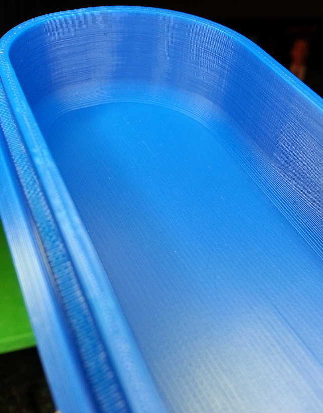
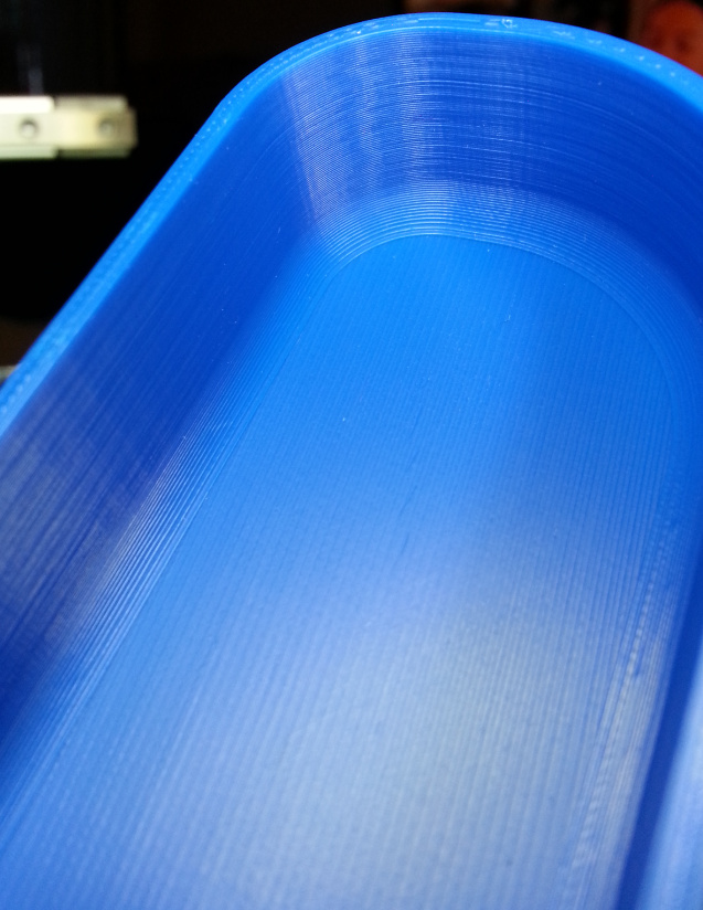
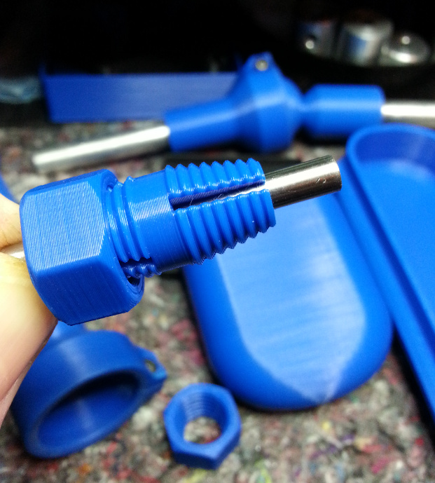
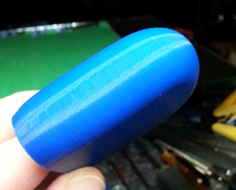
I kinda stumbled upon the next mod within the extruder setup, but wow… I mean double-wow …the quality-of-print is what you see above in the photos I posted. Am I happy yet?? …I’m frickin’ bouncin’-off-the-walls happy!! Maybe I can hire a housekeeper happy!
So here we are, I have a bunch of mods that make this printer sing, and dread the next step because this process of publishing is going to take away the distractions that allow me moments-of-freedom from the pain.
Is there more to create/engineer and solve… yes, the heat-zone is too long, I’d like at least 12mm’s of sequential printing, a reliable automatic bed leveler, an electronics hat that does not trap heat, reliable flexible filament printing, an alignment jig for x/y/z…etc etc … I have many on the list! Do I already have solutions… yes. Do I have freedom from the box-of-pain… only when I’m in the engineering and/or creation mode.
It’s not long til I release the mod-package, I’ve stopped development of any additional mods. I’m working as fast as possible to clean-up the prototypes and get some documentation going.
cheers,
Brent

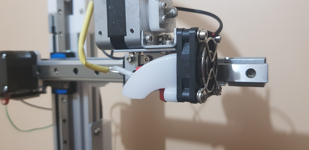
 by the way, I sort of noticed less fan noise with this duct. Is that your experience too?