I’ve seen there’s a few people who are wanting to replace the board in their UP300.
I’ve got about halfway through working out what the pins are on the connectors are, feel free to share what you’ve worked out.
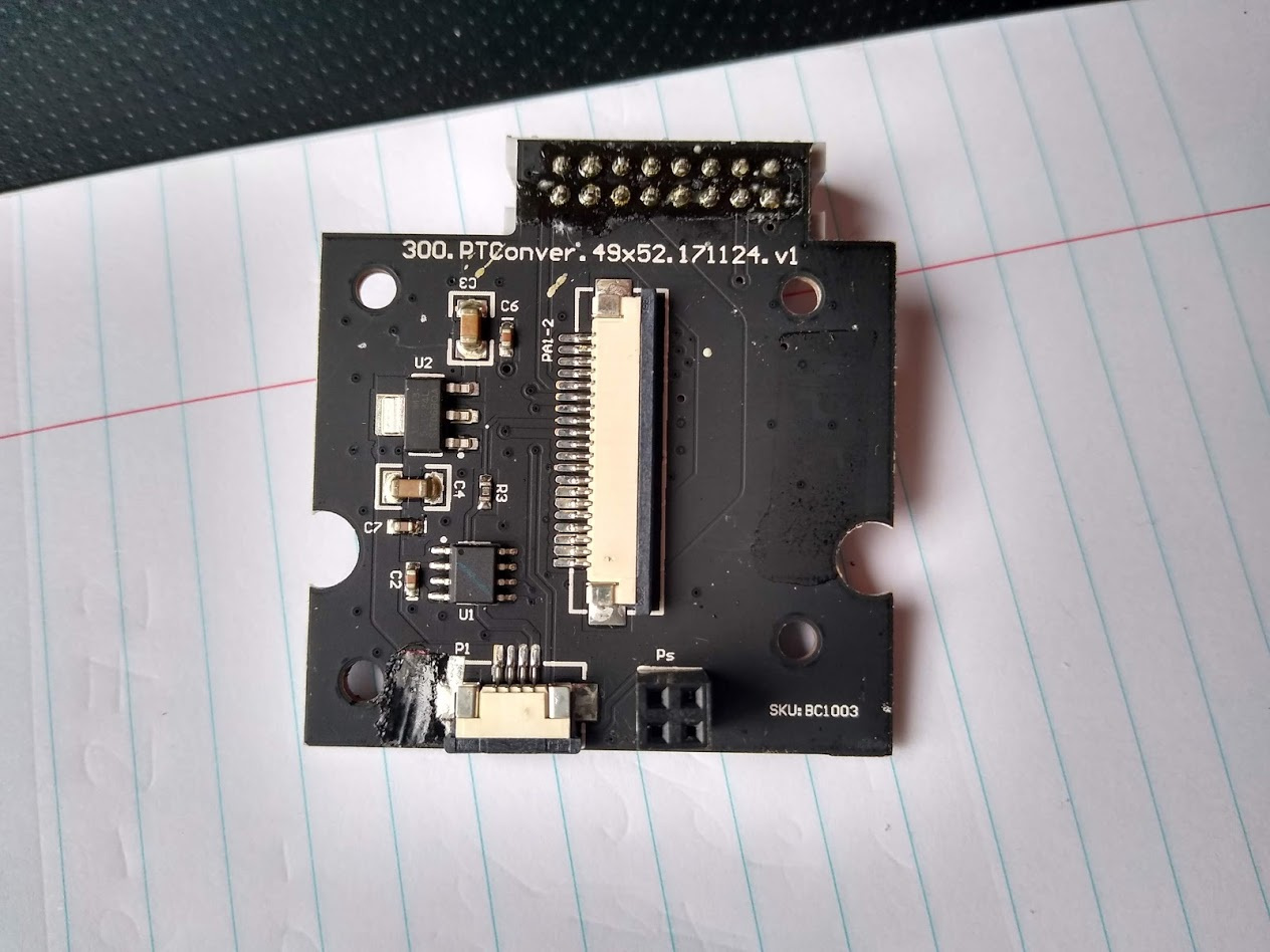
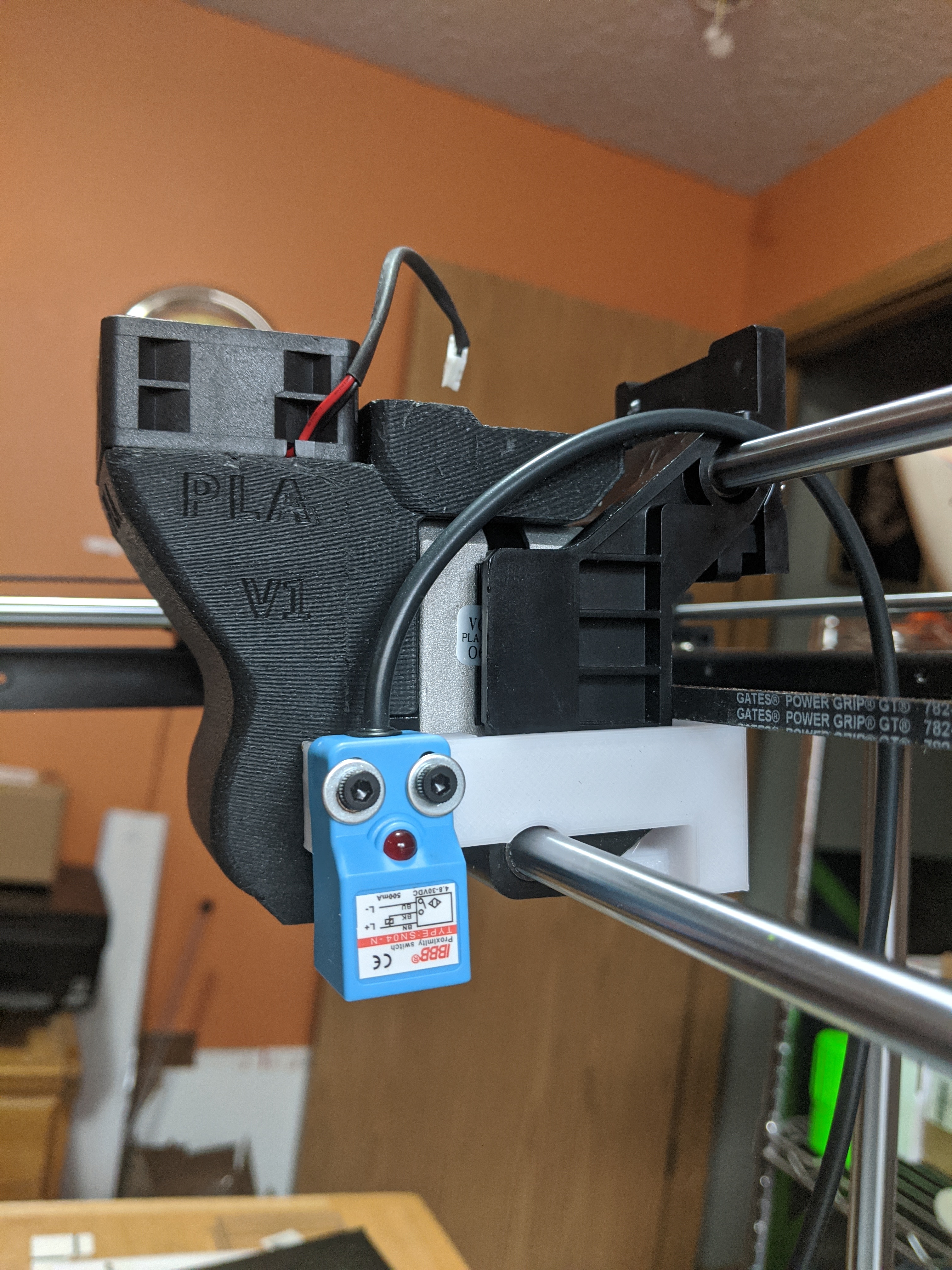
On the extruder carriage back we have this PCB:
So my approach is going to be wire in another board and do away with the original one in there completely.
I have briefly considered making a adapter board to drop in as a replacement for perhaps a arduino mega.
Perhaps the easier method of going about this would be buying a CPU from tinyfab.xyz and adapting the pinout as required, and just dropping it in as a new CPU.
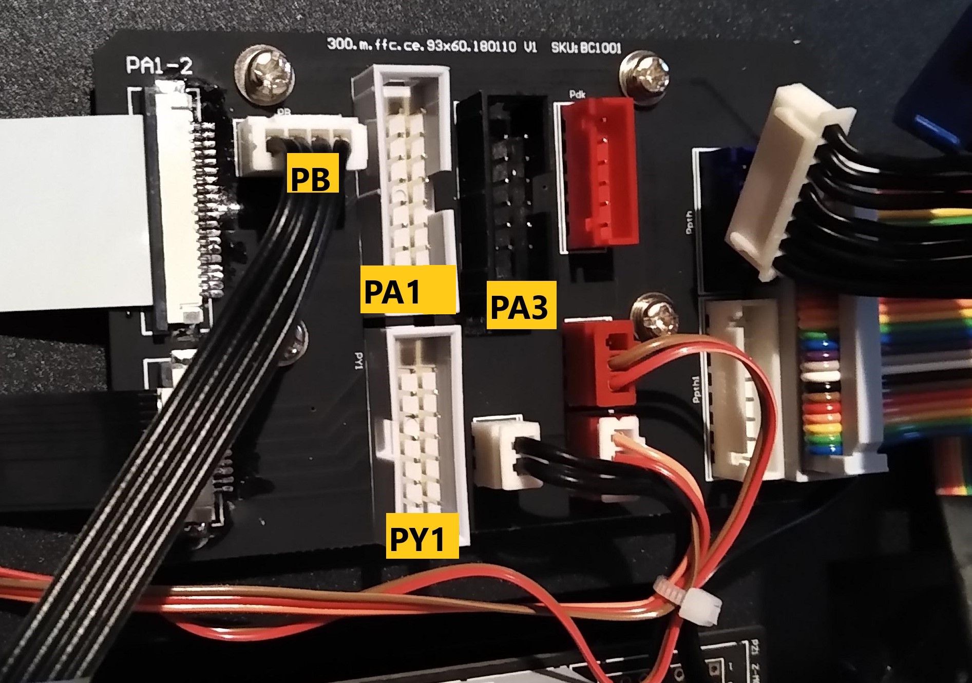
I have the relevant pinout for PY1 but I’m not 100% clear on which pin you’re calling Pin1. In the photograph, it looks like Pin1 on PA1 is the lower-right pin, which is what I have been calling pin 1. Right below the photograph, though, it looks like you started at the upper-left pin. I just want to make sure that my numbering matches yours since those two connectors are 180 degrees out from each other.
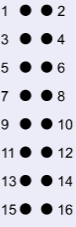
Even though these connectors are 180 degrees out from each other, I think it may be less confusing for most people if the pinouts for both are numbered the same. So, for PY1, here’s what I’ve been able to find.
1 X-motor orange
2 X-motor orange
3 X-motor blue
4 X-motor blue
5 X-motor yellow
6 X-motor yellow
7 X-motor red
8 X-motor red
9 X end stop -
10 X end stop -
11 X end stop +
12 X end stop +
13 NC
14 NC
Pin 5 on is the other pin for the hot end temperature sensor.
Pins 9, 10, 11, 12 are one side of the hot end heater
Pins 13, 14, 15, 16 are the other side of the hot end heater
*Note that the hot end thermistors are the PT100 type. In my case, since I am replacing the controller with a Duet 2 Wifi, my choices are to replace the thermistors in the hot ends with the 100k Ohm type or else add a PT100 Daughterboard. Looking at the UP300 hot ends, it looks like the thermistors are held in with a screw that was tightened and then the head was sheared off. IDK if that’s really the case but that’s sure what it looks like to me.
The thermistor for the build plate heater is 100k Ohm.
you can hook the pt100 directly to the duet 2 maestro at least, but resolution and or accuracy will suffer. you’ll find descriptions on the duet forums
I am also going to replace the controller. Most likely with Duet. I have started on a schematic for breakout board which incorporates the work from JothanB and rlkirstine and added other connections. UP300_BC1001_Board.pdf (167.8 KB)
I will update schematic as I understand connections.
Dunno how long it’ll be but they’ve talked about releasing new boards in the Duet2 series with TMC2209 drivers. If you got too much $ the Duet 3 might simplify things a little as you could probably find a combination of expansion boards to replace most of the custom wiring with just power and CAN bus.
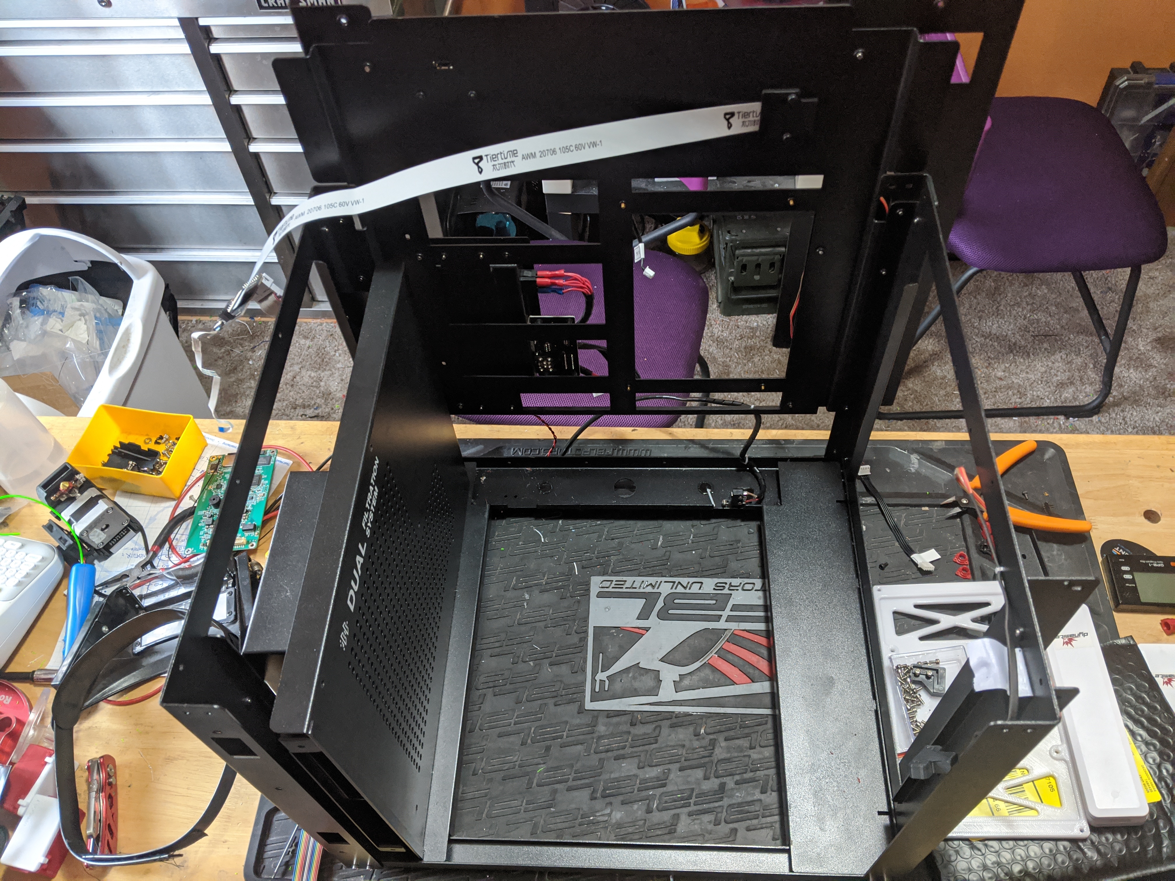
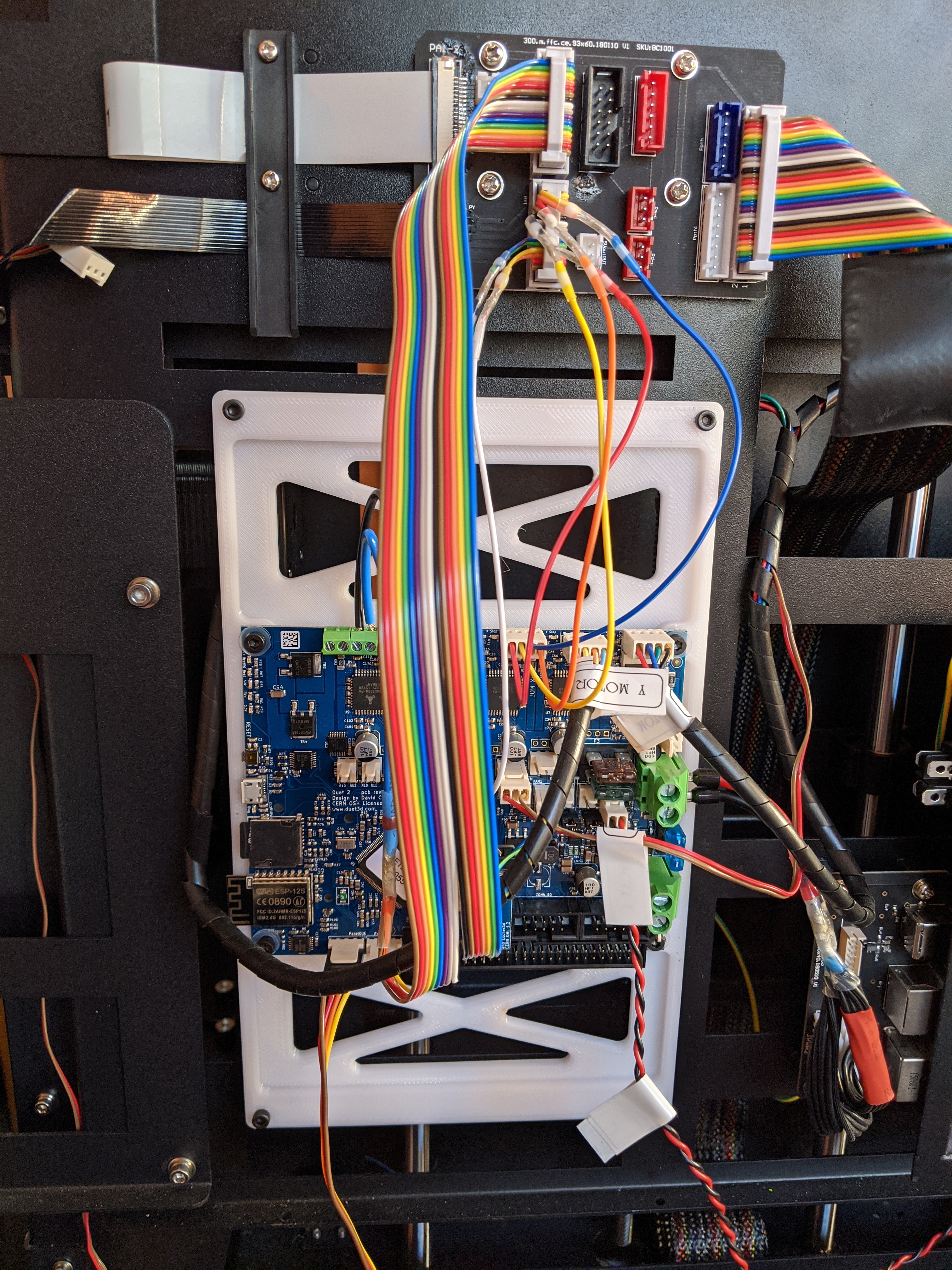
Oh, nice! I haven’t logged onto here in quite a while because my life got pretty busy. Left my job of 32 years, last year, and then started a new job not long after I was getting pretty close on completing my upgrade. It’s been on hold for a while but I did get as far as installing the new Duet2 WiFi controller and getting everything except for the heated bed working. I was able to connect to the Duet2, home the motors, move them, etc… With your schematic, it will be really easy to complete my upgrade now! Here’s what the back looks like now that I have the controller installed and mostly wired.
I have done more tracing on the existing controller and updated the schematic.
Did you work out how the servo is driven? I cannot find where the servo signal wire ends up. UP300_Boards.pdf (329.0 KB)
I have not yet started on conversion to Duet2 but have been hacking the heated bed wiring with 16 AWG wire and XT30 connectors. I have also tested new wiring and heated bed sitting on bench and can get to about 103 degC (measured on the top of the bed covered with Perf build plate). It took 50 minutes to reach this temperature (room temp about 20 degC). I am not happy with the slow heating rate and wanted to increase power. To allow this I have built a circuit with opto isolated interface and MOSFET which uses the existing heated bed output and allows the new MOSFET to power the heated bed with higher voltage/current. Initially I am going to use 31V but when I get different power supply use 36V. This will give initial input power of about 288W but it will quickly drop to about 208W as the bed heats up.
Thank you for all informations shared here !!
uselly i work with a Alfawise U20, 0,06 Z layer and Gcode
i just bought an UP300, but didnot check before for gcode…
so i try to do what you did !
someone could share again “UP300_Boards.pdf” it isnot available anymore…