HOWTO: Cura w/ Cetus3D

cmeyer 2017-4-6 03:09 edit

!!CAUTION!!

- make sure your nozzle offset is correct in the starting g-code

- the nozzle offset may be different than in Cetus Studio. Do the paper test and use a gcode file something like this:

p.p1 {margin: 0.0px 0.0px 5.0px 0.0px; font: 16.0px Helvetica; -webkit-text-stroke: #000000} span.s1 {font-kerning: none}

G1 Z0 F9500

G1 X0 Y0 F5500

G28 Z-2    ; home Z axis

G28 X-2 Y2 ; home x y axes

M206 X-180   ; offset X axis so the coordinates are 0..180

M206 Z-182.3 ; nozzle offset (TUNE before using!!)

G1 X90 Y90 F5500

G1 Z0.0 F5500

- re-run this gcode file over and over, each time slowly changing the nozzle offset (just like you would in Cetus Studio) until it passes the paper test

- I found mine to be different from the one determined in Cetus Studio, it appears the G28 comes up with a slightly different result than the native implementation

- Cetus Studio does not currently use the calibration (not nozzle offset, not anything else) when running g-code, so make sure your Cetus is squared, build plate level, etc. Otherwise you risk scratching your build plate!

- if your machine is not squared up, your nozzle offset will vary across the build plate, so to avoid scratching it, you'll need to use a nozzle offset that works across your whole build plate

- don't run g-code blindly, since the nozzle offset is built-in, it's only re-usable on the same printer and only if the offset hasn't changed


See my notes on getting slic3r running with Cetus Studio: https://www.cetus3d.com/community/forum.php?mod=viewthread&tid=268


Based on that, I've evolved my starting g-code snippet to allow me to use Cura. To set up Cura:

- Add a Custom FDM Printer (name it Cetus)

- in the machine settings set widthxdepthxheight as 180x180x180

- in the machine settings set your nozzle size

- in the machine settings I've set all the print-head settings to 0, haven't experimented with that

- start Gcode:

G28 Z-2        ; home Z axis (first for safety)

G28 X-2 Y2   ; home X Y axes

M204 P1500  ; set acceleration


M206 X-180   ; offset X axis so the coordinates are 0..180

M206 Z-182.5 ; nozzle offset (TUNE before using!!) so the bed is at 0

- end Gcode:

M109 ;switch off extruder

M191 ;switch off heated bed

G28 Z-2; home Z

G28 X-2 Y2; home axes

M2 ;end of program

- in the machine settings set the GCode flavor to RepRap Marlin/Sprinter

- I used UnmotivatedGene's printing profiles as a starting point: https://www.dropbox.com/sh/1hahpdgj0l685vl/AADXj0evTDDH3m4WKBMxfBKNa?dl=0 see the reddit thread where he posted that here: https://www.reddit.com/r/cetus3d/comments/5re142/cetus_with_cura_or_simplify3d_other/ 

- in the print setup you'll have to set the flow rate ridiculously high. I haven't tuned this, yet, I'm currently at 2200%

- in the print setup I had to disable retraction because it just kept retracting instead of starting the print


To print:

- load a model in cura, save g-code

- in Cetus Studio load the Gcode file and print

- Gcode does not give you progress reports, but you will see the temp readings

- to stop a print go to Maintenance->STOP (where the Extrude/Retract buttons are)


Important!

- Make absolutely sure you have the nozzle offset in the start Gcode set appropriately for your printer (based on calibration)

- Make sure your bed is level and your printer square!


The same approach should also apply to other slicers such as KIS Slicer (haven't tried) and I've already confirmed it works with slic3r (see other thread linked above).


Here's what a 20x20 calibration cube looks like on first try with Cura (2200% flow rate), left cube is Cetus Studio normal speed, right cube is Cura w/ UnmotivatedGene's CetusNormal profile (and my flow rate & retraction change mention above):
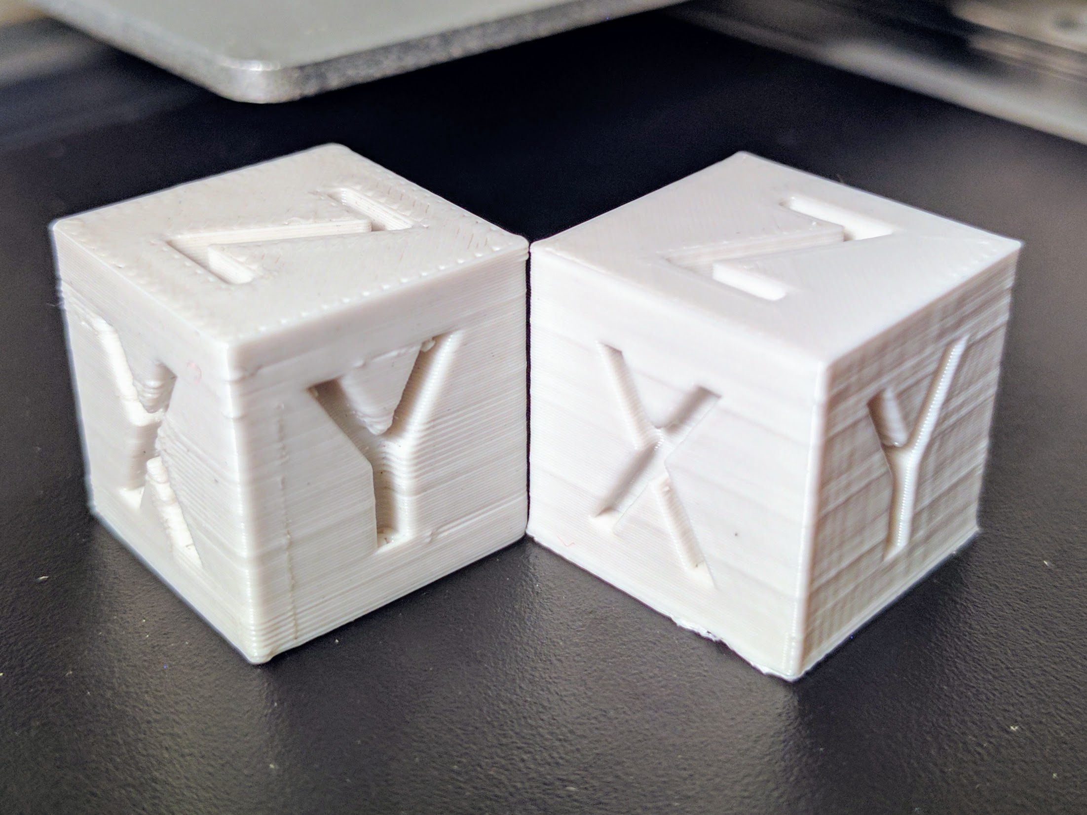
IMG_20170404_213043.jpg


For Cura I had left the Brim on which is why the bottom edge is not clean.

So I've found that the G28 gcode implementation comes up with a slightly different calibration than when I use the Cetus Studio "Initialize Printer" or the button. Make sure you check your nozzle offset for running gcode separately from your nozzle offset in Cetus Studio.


You can do so by running a simple gcode script multiple times, slowly approaching your nozzle offset, just the way you do in Cetus Studio. An example of such a script would be:

G1 Z0 F9500

G1 X0 Y0 F5500

G28 Z-2    ; home Z axis

G28 X-2 Y2 ; home x y axes

M206 X-180   ; offset X axis so the coordinates are 0..180

M206 Z-182.3 ; nozzle offset (TUNE before using!!)

G1 X90 Y90 F5500

G1 Z0.0 F5500


You start with a nozzle offset you know is definitely clear of the plate, then slowly approach the plate. Increase by 0.1 for example, the way Cetus Studio does. Perform the same paper test you do in Cetus Studio.


I ended up with a nozzle offset of 182.5 (passes paper test), whereas in Cetus Studio I come up with 183.2.

I also experimented with figuring out how much material is actually being extruded. I found that running the gcode G1 E2250 extruded 100mm of filament, so the current gcode transcoder is off by a factor of 22.5. I noticed that M92 is part of the list of support gcodes, see kickstarter update: https://www.kickstarter.com/projects/854865943/cetus3d-at-199-get-all-you-need-to-start-3d-printi/posts/1679083 so theoretically it should be possible to correct the ratio so that the correct amount of filement is extruded. Unfortunately including an M92 Exx instruction made no difference whatsoever on the amount being extruded.

It's been pretty quiet here, so I just wanted to jump in and say thank you for all the work you put into this! I've been using Simplify3D but have still been keeping a close eye on Cura and Slic3r support. 


Knowing the 22.5 factor also helps things quite a bit.


Thank you!!!

msim, curious to hear what starting gcode you like to use?


Due to the inaccuracy / unreliability of G28, I'm now getting rid of it in mine and using the Initialize Printer button in Cetus Studio, until the two produce the same result.


What that means, of course, is that I determine the nozzle offset in Cetus Studio as per usual using the paper test method (though depending on how I print I don't do the -0.5), removing the two G28 lines from both my start/end g-code, and changing the M206 Z-182.3 line in my starting gcode to use the value I determined in the calibration dialog of Cetus Studio.


Though I've been getting consistent results with G28, they've been consistently off from Cetus Studio. And since they appear to be obtained at a faster speed, they're probably less accurate (error +/-) and not just off.

Are you doing the paper test w/ Cetus Studio or with gcode? The nozzle height unfortunately comes out different right now.


So if you keep the G28 in the start gcode, you need to make sure you've measured the nozzle height with some gcode that has G28 in it.


If you're using the Cetus Studio nozzle height, you need to remove the G28 from your start/end gcode.


The start code I'm currently using (make absolutely sure you have the Z (height) set to your nozzle height) -- I use the calibration from Cetus Studio:


; !! Machine height MUST be set to your nozzle height !!

M206 Z-{machine_height} ; offset Z axis so the bed is at Z0, without this, the bed is at Z-{machine_height}

M206 X-180   ; offset X axis so the coordinates are 0..180, normally they are -180..0


M204 P800   ; set acceleration


G1 X2 Y178 F5000 ; move to back right corner

G1 Z0.6 F1000 ; get nozzle close to bed

G92 E0 ;zero the extruded length

G1 X50 E360 F300 ; extrude a 5cm purge line

G92 E0 ;zero the extruded length

G1 E-11.25 F2700 ; retract a little


I'm still mostly using 2250% (22.5), but I've seen some people use 2400% (24), personally I'm experimenting with 2360% (23.6) right now, I picked up on that idea here: https://github.com/UP3D-gcode/UP3D/blob/master/UP3DCOMMON/up3dconf.c


But I think I have to go back and try my actual filament extrusion experiment again to see if I measured correctly the first time or not.

Thanks for this guide! It worked really well and my prints look a lot better now.


As said by Cetus, I would like to add that the mkII owners should leave the G28 out of the code. As the initialisation does that for you.

Giving this a try.  FWIW, I took some time and made some measurements (+1-2mm) for the printhead settings (collision-box), with the stock parts:


X-Min: 56mm

X-Max: 38mm


Y-Min: 32mm

Y-Max: 56mm


Gantry-to-nozzel: 6mm


Can anyone confirm 2360% or 2250% ?

Okay, after some bed-scraping, I've got this working, though certainly not as nice a print as from Cetus3D Studio, I've got TONS of parameters to play with now.  I didn't try the 2250%, but I did notice that it really messes with the 'line/path' display.  Is there another parameter/setting which could be used to specify the extrusion-motor compensation factor w/o messing up the line/path preview display?

FWIW, after scratching up my plate slightly, I'm...


Using Start code:

M206 Z-277.6 ; Customize this for actual value

M206 X-180   ; offset X axis so the coordinates are 0..180, normally they are -180..0

M204 P800    ; set acceleration


G1 X5 Y5 F5000 ; move to back right corner

G1 Z0.6 F1000 ; get nozzle close to bed

G92 E0 ;zero the extruded length

G1 X25 E360 F300 ; extrude a 2cm purge line

G92 E0 ;zero the extruded length

G1 E-11.25 F2700 ; retract a little

G1 X80 Y80 Z50 F5000 ; Move to Center, off bed


Using End code:

G1 X0.0 Y0.0 Z277 F5500   ; Safe place

M109       ; switch off extruder

M191       ; switch off heated bed

M2         ;end of program


I just wanted to thank everyone who contributed to this thread - it helped me tremendously when setting up my Cetus3D MkII with Cura.

Perhaps the info below will help someone in the future:

a) I used the start and end code from chrisevich (#11) which worked nicely for me.

b) the z-axis calibration code posted by cmeyer never worked for me. I did compile my ‘own version’ from the start code by chrisevich. This one worked. (I think a painfully precise calibration is overkill. If you use a brim around a test-model in Cura, the correct height is achieved, if the individual lines that make up the brim squash together nicely. The nozzle is too close to the bed, if the brim thickness (z-direction) gets to thin and translucent. The nozzle is too far away from the bed, if the individual lines can be easily separated and do not stick together.)

c) Up Studio allows for an 9-point calibration routine for the z-axis. Cura seems to be unable to do that. Keep in mind that you may have to find a physical solution for levelling the build bed when using Cura.

d) With the current version of Cura (v3.3.1) it is better to adjust the flow rate of molten filament via the filament diameter, than the flow rate percentage. Flow rate percentage adjustments mess up the ‘layer view’ in Cura (from years of experience with an Ultimaker 2, I find this one of the most helpful features in Cura). Filament diameters of around 0.38 translate to the 2200% cmeyer posted (flow rate factors in quadratic, so use fine steps when adjusting it). I have better results with lower flow rates (dia 0.4 or 1900%), but more testing needs to be done.

m.

<p>Hi, I have packed the suggestions found into this topic (and some more stuff) into a post processing script for Cura.</p><p>You may want to give it a shot: https://github.com/dpellegr/Cura4Cetus</p><p>Feedback is welcomed!</p>

Hello Dariop,
I check out your script and it’s very interesting ( that u flip the axis do for upstudio). I think this script will work for my mini 2. My build volume is 120x 120x 120 and I know my Z offset height is typically around 123.
Can you tell me where I have to make adjustments in the script to suite it to my build profile ??