@techsalad Hi Brent, will your website get updates soon?
@Arnold Hi Arnold, I’d love to just post all the mods and methods allowing this affordable printer the insane accuracy from a cantilever style printer. And the print-speed increase is crazy!
I suppose I must provide a little background to understand the snails-pace this project is suffering from…
Fourteen years ago a car accident completely changed my life and many doctors said I would never work again. But as we humans do, we survive, adapt, and if a passion is strong enough… we sometimes overcome our disabilities for a few hours a day. My days are broken-up into three or four 1.5 hour sessions of being vertical, the rest of my conscious time is horizontal meditating to lessen the effects of extensive soft-tissue damage the length of my spine. Some days I’m blessed to enjoy a little more time to think past the pain, but those days are rare.
This mod project started out with a robust z-axis stiffener, it had to be bolt-on and easy to install. My z-axis is solid, the weakest link now is the stainless steel base everything attaches to, but I also have a solution for that problem. The z-axis mod definitely improved the print quality, but not enough to satisfy me.
My attention focused on the y-axis structure. Four more mods were created, and the print quality improved and higher print-speeds attainable. But again, I was not completely happy. I already knew the extruder motor ran too-hot and being a two-phase stepper it had to rotate far more than a four-phase to achieve the same move. I thought I should publish my findings to this point to help others with their printer woes, started to organize the mods and document methods/procedures but the pain quickly invaded… not enough distraction from the pain. Focusing on the extruder setup got me back into the zone of less pain, so I dealt with the axial torque and the overheating extruder motor. Rock-solid motor mount, waaaay less heat and more torque… excellent. Even higher print-speeds, this is where I broke through the 90mm/sec limit, printing faster with very little loss of quality-of-print. The surface artifacts had decreased substantially at this point, but yeah…still felt there was more I could tackle and solve.
By this point in the project I had poured a ton-of-time into creating/engineering solutions for this little printer with so much potential, and forgot about the cost to my financial stability as a disabled person desperate for a better quality-of-life. This project has given me so many moments of less pain… I had become addicted to product-development and prototyping. So, as you can imagine, nothing else gets done around here!
I kinda stumbled upon the next mod within the extruder setup, but wow… I mean double-wow …the quality-of-print is what you see above in the photos I posted. Am I happy yet?? …I’m frickin’ bouncin’-off-the-walls happy!! Maybe I can hire a housekeeper happy!
So here we are, I have a bunch of mods that make this printer sing, and dread the next step because this process of publishing is going to take away the distractions that allow me moments-of-freedom from the pain.
Is there more to create/engineer and solve… yes, the heat-zone is too long, I’d like at least 12mm’s of sequential printing, a reliable automatic bed leveler, an electronics hat that does not trap heat, reliable flexible filament printing, an alignment jig for x/y/z…etc etc … I have many on the list! Do I already have solutions… yes. Do I have freedom from the box-of-pain… only when I’m in the engineering and/or creation mode.
It’s not long til I release the mod-package, I’ve stopped development of any additional mods. I’m working as fast as possible to clean-up the prototypes and get some documentation going.
cheers,
Brent
Hi Brent, thanks for sharing a bit of your background! Your prints look really amazing and I’m very looking forward to see how you achieved all of this! I did some minor mods and improvements on my Cetus MK3 setup, but mostly peripheral ones. I can totally relate how designing/prototyping pulls you in a zone and happy that it helps you push your pain in the background for a bit! All the best to you in the meantime!
PS: Can you add a link to your website in your profile? I have trouble finding it…
1 Like
@superhans , profile is updated… I was trying to avoid any attention to the website, it’s extremely basic and not interactive as yet.
Tks for taking the time to understand why this project has been so slooooow to publish, wish I could wave-my-hand and poof …done …and many folks unleashing the full-potential of this little printer.
I have another printed model pic to share…yesterday I mounted a .2mm nozzle which I hadn’t used since purchasing the printer last year and not since sparking-up Simplify3D. The printer’s firmware is compensating for something…after calibrating z, and loading a gcode file from S3D, UpStudio was printing in air at .10LHeight. Normally, I print without any software tricks, rafts, supports etc etc… just a brim on an optical mirror with green painter’s tape and the extra length of the green painter’s tape is sandwiching the mirror to the stock build-plate with 20+ brass shims in-between. After offsetting z by .10mm …still printing in air, lacking the time investigate I printed at .15LHeight and .25LWidth…just barely tho. I’ll post the pic soon, need a flat-black background to show-off the crisp edges.
cheers,
Brent
1 Like
First few prints failed as mentioned in above post and having very little experience using a .20mmNozzle 10mmLayerHeight .25LineWidth, my build-platform leveling strategy required a more aggressive procedure.
Removed the green painters tape and calibrated within UPStudio using a .04mm sheet of paper from my Engineers Pocket Reference…yikes …but no worries, used a page from the perpetual calendar  . The setting at each calibration point… paper is barely movable without tearing.
Re-applied green painters tape and used spatula to lightly smooth the peaks and valleys.
Back into the 9 point calibration using a .02mm brass shim and setting at each calibration point…cannot move the shim without tearing and no-dimples in shim. Confirmed the calibration procedure using the exact height as determined using the shim. No offsets or adding/subtracting from the exact height, this nozzle height is used in S3D and UPStudio. Loaded a dummy stl file into UPStudio and right-clicked to delete all models. Restarted UPStudio and performed an extrude cycle to check for moisture in the filament and nozzle heat-zone. Good-to-go…
Next post will show the print result, please keep-in-mind I do not care about bridging fails, small artifacts resulting from layer-changes or any other surface-quality fails controlled by tweaking print-profiles in software/firmware. For me, and the scope of this project, the measure of pass/fail is determining if the hardware mods I’ve created are providing the hardware backbone of the 3D print-process allowing for extreme accuracy and higher print-speeds in excess of 100mm/sec.
Cheers,
Brent
Technology Salad
@techsalad, admirable story you have there. In another forum, we also have another disabled person who’s into 3D printing.
1 Like
@Arnold , the person you’re referring to …did he/she have an accident and the printer toppled onto the floor creating extensive damage?
@techsalad, well we talked about our eyes  he’s legally blind on one, so I am still in a better shape with my left.
Couple of tough days, sorry for the delay folks…
So, after the aggressive build-plate leveling procedure mentioned above, I wanted to see how accurate this modded MKII could print at .05mmLHeight x .25LWidth using the stock .20Noz.
Fired-up S3D and loaded SyntaxGeek’s .20Noz S3D-profile (Thingiverse-3035906), a remix of @antoledcetus amazing S3D profile also available from Thingiverse. Huge shout-out to @antoledcetus for his S3D .40Noz profile, I used his profile to print the models shown above in an earlier post.
Loaded Thingiverse-2039065 (this is the coupler and nut as shown in an earlier-post above printed .40Noz .20LHeight .40LWidth 65mm/sec). Attempted .05mmLHeight x .25LWidth using the stock .20Noz. No-go, too many settings to dial-in .05LHeight on the .20Noz, It’s the extruder flow-rate that needs tweaking, just don’t have the time to investigate.
So here’s the coupler printed with .20Noz at .10LHeight x .25LWidth at 40mm/sec.
no supports, no raft, no brim…just those 3 tiny pillars you see at the top of the coin.
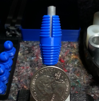
edit: I know, crappy photo, I just can’t get past the pain right now, sry folks.
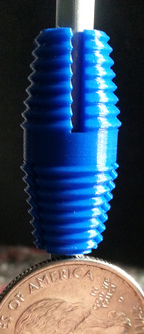
edit: below, better photo showing profile of coupler:

cheers,
Brent
Technology Salad
1 Like
Looks like a pretty nice print!
1 Like
Tks for the feedback @bjorn , difficult to show the profile while keeping overall focus but also trying to display the layer lines. A shallow depth-of-field while in macro mode because of the taper, need a 3D camera to properly photograph this type of subject 
Here’s the coupler printed with .20Noz at .10LHeight x .25LWidth at 40mm/sec.
- no supports, no raft, no brim…just those 3 tiny pillars you see at the top of the coin.
cheers,
Brent
Technology Salad
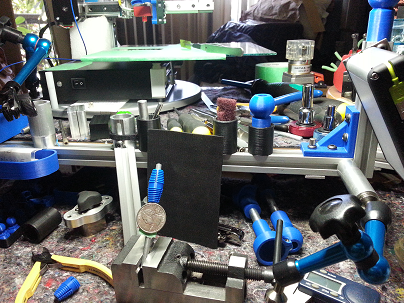
Thought it might be fun for you folks to see a portion of my CAD workstation for the Cetus3D mod project. To the right are two 24" CAD monitors, a 21" Wacom Cintiq Artist Tablet and many more tools-of-the-trade.
There is a slight teaser of my heavily modded Cetus3D MKII in the photo …enjoy 
cheers,
Brent
Technology Salad
Thanks Brent for the updates, the 0.2 mm prints look magnificent! Still very looking forward to your mods, but no pressure, just Vorfreude! 
I received the heated bed upgrade parts for my Cetus MK3 today, so some fun stuff to tinker with in the coming days.
1 Like
@superhans , And thank-you for the feedback Andreas. I’m also Vorfreude!
You know Andreas, I’m a little puzzled these days. A few months ago, when I was in frequent contact with a few of the support staff at Tiertime regarding the mods I was developing, I mentioned I had found a way to further stabilize the y-axis with two bolts. They could implement the method at the factory and no-one would ever notice the mod was in place. You would have to know it was there to discover it, seriously, it just blends into the existing hardware and looks like it’s just another bolt-head performing the fastening-job the others are. I offered the mod as a trade-secret and said I would sign an NDA to complete the trade-secret circle-of-knowledge…no reply to-date.
I’ve been participating in the 3D printing industry for 7+ years now, and I continue to be amazed at the continued use of precision components attached to structural components not-so-precise. I know, it’s a balancing act to compete in the marketplace… money money money makes the world turn…capitalism vs product evolution… the razor’s edge.
edit: Enjoy the new heated-bed upgrade, I can see your perma-grin in your forum-post!
Anyway, back to work…cheers, Brent
@techsalad Yeah it’s really puzzling when people like you, who have a lot of experience in the field, happily contribute to a better product and it’s not even considered… And sure, it’s always a trade-off, but if a few printed pieces or other cheap parts can make a significant difference, you have to wonder…
I entered the 3D printing space since beginning of 2019 and am really amazed by the community so far. Very welcoming, lots of sharing, it’s fairly easy to contribute.
Still in the process of installing the heated bed. Although I’m puzzled by two printed parts that where included… No documentation/manual available, oh well.
1 Like
I enjoy tackling the unsolvable, the more difficult the better for me… send me a photo, private message me if you prefer.
If just a fraction of the world took their challenges with your stride I think the world would be a better place.
2 Likes
@techsalad Cheers! I commented here with photos: https://support.tiertime.com/hc/en-us/articles/360023111253?page=1#comment_360002149073 The main issue is the replacement bracket, if it must be used. It has a dent that looks intentional and probably improves the structural stability of the bracket, but makes it impossible to mount it flat and not angled. Thought about designing a spacer between the bracket and the bearing block to allow for even and firm mounting. The printed parts are another puzzle, but less relevant I suppose. I thought the one with the hole might be a spacer, but it doesn’t fit for that purpose…
Thanks for the words guys, really makes a difference for me hearing them… most certainly propels me to continue despite my physical burdens. Cheers, seriously!
1 Like